
Dr.-Ing. Jörg J. Buchholz
Institut für Flugmechanik
DLR Braunschweig
joerg.buchholz@dlr.de
This paper presents a real-time, pilot-in-the-loop, visual, PC-based simulation program of a REVOLUTION® kite. The pilot uses the mouse to emulate both handles and follows the motions of kite, lines, and handles on the screen.
A detailed description of the aerodynamics and kinematics of the kite model to be simulated will be followed by some interesting real-time implementation aspects and man-machine interface problems. Stability questions will be addressed as well as a simple autopilot to assist the inexperienced pilot.
There used to be a time, when every father would build a diamond kite for his son in autumn, wrapping one page of an old newspaper around a hand carved wooden cross and ripping the rest of the newspaper into a long tail for stability. Well - those days are definitely gone.
Modern high tech kites are composed of materials like Dacron, Nylon, Tyvex, Mylar, fiberglass, wrapped carbon, titanium, Kevlar, Spectra, ... coming from space research labs and aircraft manufacturers. They are optimized for weight, speed, durability, controllability, and fun. It is not unusual for kite enthusiasts to pay hundreds and even thousands of dollars for an extraordinary kite. There are very active kiteflyers associations all around the world, holding fighter, sport, and stunt kite competitions and world championships with international rules. Kiting has developed from a pure child's toy to a fascinating and challenging sport.
The REVOLUTION® is one of the most interesting modern kites. As shown in Fig. 1, the kite basically consists of two triangles that independently rotate around a common leading edge spar.

Fig. 1 REVOLUTION® kite
Four lines connect the ends of the spreader spars to two handles the pilot uses to control the angles of attack of both triangles independently. Having full authority over the lift forces on both sides of the kite, the pilot can not only accelerate the kite into any desired direction, but also stop, fly backwards, sideslip, or rotate the kite at any given position.
These fascinating kinematics and seemingly uncomplicated aerodynamics make the REVOLUTION® an ideal candidate for modeling and simulating it on a computer.
RevSim (the Revolution Simulator) is the final outcome of many hours of "visual identification” on the field and the beach, lots of discussions with expert colleagues and a few days of C-coding. It is not a project of DLR, but a private "hobby” of the author who definitely has no commercial intentions with this program.
Most symbols and names have been chosen based on DIN 9300 (ISO 1151). Vectors and matrices are in bold type (with the corresponding vector magnitudes in non-bold type).
| (Normal vector on) plane | |
| Bias vector | |
| Spreader spar vector | |
| Total force | |
| Handle vector | |
| Rolling moment | |
| Center (of gravity) vector | |
| Aerodynamic force | |
| Line vector | |
| Leading edge vector | |
| Kite velocity vector (center of gravity relative to air) | |
| Flight-path velocity vector (center of gravity relative to earth) | |
| Wind velocity vector (air relative to earth) | |
| Leading edge velocity vector (leading edge relative to earth) | |
| Imaginary handle connection vector | |
| Damping coefficient | |
| Intermediate axis | |
| Mass | |
| Integration time interval | |
| Auto pilot controller gain | |
| Elevation angle | |
| Azimuth angle | |
| Stability angle | |
| Handle roll angle around the line | |
| Kite roll angle | |
| Handle pitch angle | |
| Handle roll angle | |
| Handle yaw angle | |
| Air density | |
| Indices | |
| d | Kite-fixed |
| g | Earth-fixed |
| h | Handle-fixed |
| l | Left (side) |
| r | Right (side) |
| s | Line-fixed |
Probably the most efficient way to model the dynamics of a complex moving system is to:
Four main axis systems are necessary to describe the dynamic behavior of a REVOLUTION®:
At least three transformation matrices have to be defined between the four axis systems:
Axis systems and transformations will be described in detail in the next chapters. All axis systems are right-handed (thumb: x-axis, index finger: y-axis, middle finger: z-axis) and expressions like "down” or "right” refer to pilot and kite on ground just before regular take off (leading edge up).
The kite-fixed axis system defines the attitude of the kite.
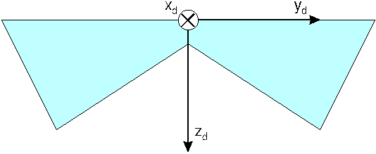
Fig. 2 Kite-fixed axis system
As the REVOLUTION® consists of two sail triangles that independently rotate around the common leading edge, actually two kite-fixed axis systems have to be defined (one for the right sail and one for the left sail). As a consequence both axis systems share the same y-axis.
In this simulation the earth-fixed axis system has the function of an inertial or
reference system. Taking into account the low speed and travel distance of the kite, earth
curvature, rotation, and motion can very happily be neglected (flat
inertial earth).
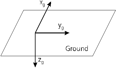
Fig. 3 Earth-fixed axis system
The line-fixed axis system is defined by the direction of the lines between pilot and kite. For the definition of this axis system all four lines are substituted by one imaginary line between the pilot and the kite.
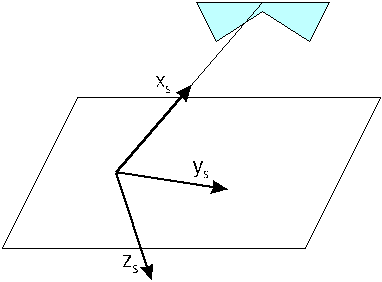
Fig. 4 Line-fixed axis system
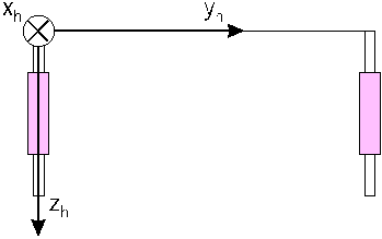
Fig. 5 Handle-fixed axis system
As with the kite-fixed axis system(s), actually two handle-fixed axis systems have to be defined; one for the right handle and one for the left handle. Once again both systems share the same y-axis (the imaginary connection between both upper handle ends).
Since the -axis of the line-fixed axis system is defined in the
earth's
-
-plane, only two angles (azimuth
angle
and elevation angle
) are necessary
for the transformation between earth and line.
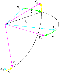
Fig. 6 Transformation between earth and lines
Being a wind-powered, tethered flying device, a kite can usually only fly on a quarter sphere, thus resulting in restrictions for the angles.
The resulting transformation matrix can be obtained by multiplying the single transformation matrices
(1) 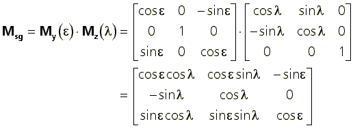
The transformation into the other direction (from line to earth) could either be done by using the negative angles and exchanging the order of the single transformations or simply by transposing the original matrix:
(2) 
The two angles directly define the position of the kite in spheric coordinates (with the constant line length s as the third coordinate).
Line vector in line-fixed axis:
(3) 
Line vector in earth-fixed axis (position):
(4) 
The transformation from earth to handle consists of three angles (handle roll angle , handle yaw angle
, and handle pitch angle
). With the assumption of a connection between the upper handle ends,
and
are the same for left and right handles;
only the pitch angle has to be distinguished for both handles (
and
).
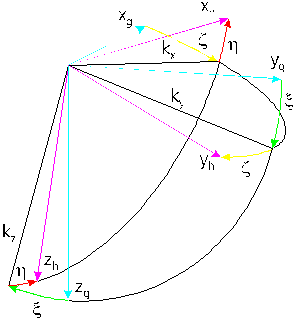
Fig. 7 Transformation between earth and handles
The restrictions in the handle angles result from the physical limitations of the pilot.
The complete transformation matrix is calculated similar to
(5)
Unfortunately the transformation from handle to kite is a bit more tricky. A few assumptions have to be made in order to come up with a relatively easy model to be implemented. First, the length of the handles (which are supposed to be straight) equals the length of the vertical spreader spars, or the vertical bridle distance, respectively. If additionally all four lines have the same length and the leading edge and the imaginary handle connection are parallel to each other, then handle and corresponding spreader spar are always parallel to each other too, no matter where the kite is positioned. Handle axis system and kite axis system are identical. The pilot directly controls the motion of the spreader spars without any dynamics involved. All this is true and only true as long as the leading edge is parallel to the imaginary handle connection. It even works, if handles and kite have rolled for the same angle.
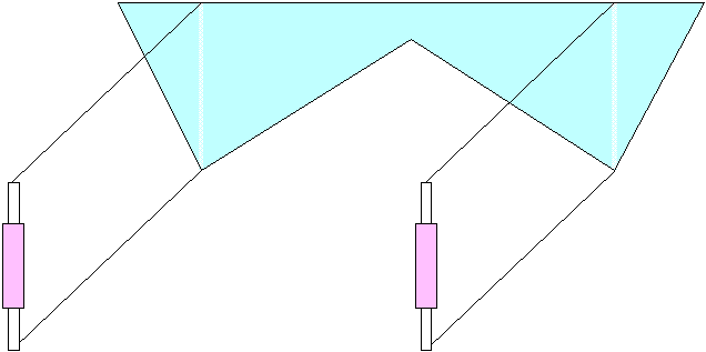
Fig. 8 Handles and spreader spars are parallel to each other
Handle and kite axis systems will only differ if there is a so called stability angle between leading edge and handle connection (the name
"stability” angle will be explained later). Unfortunately this stability angle
does not rotate around any axis of the handle axis system or the kite axis system, but
around the line-fixed
-axis. A transformation matrix
therefore first has to transform into the line-fixed axis system, then
perform the rotation around the
-axis and then transform back into
the original axis system
(6)
The back transformation only differs in the orientation of the stability angle
(7)
Alternatively quaternions could be used. This will be considered in the next version of RevSim.

Fig. 9 Axis systems and transformations
Fig. 9 combines all defined axis systems and transformations in one diagram.
Fig. 10 shows the overview block diagram of the simulation model that has been implemented in RevSim.

Fig. 10 Block diagram of the simulation model
The transformation block uses the handle angles (,
, and
) and the kite's states (
,
, and
) as arguments
of the transformation matrices in order to transform vectors from their "own”
axis system into other axis systems.
The line is transformed from the line-fixed axis system into the earth-fixed axis system
(8) 
An earth-fixed bias, representing a pilot's pulling or pushing of both handles is added to result in the center of gravity vector in earth-fixed axis
(9)
The imaginary handle connection vector is transformed into the line-fixed axis system
(10) 
where the handle roll angle around the line can be calculated
(11) 
The stability angle is the difference between kite and handle roll angle around the line
(12)
With the stability angle the transformation of the leading edge vector can now be performed from the kite-fixed into the line-fixed axis system using Eq. (7)
(13) 
Now the leading edge vector transformation into the earth-fixed axis system is very easy
(14)
Transforming the spreader spar vector from the kite-fixed into the earth-fixed axis system can be done in a similar manner
(15) 
with the one difference, that there are two handles, thus two handle pitch angles and therefore two spreader spar vectors (left and right kite sails).
Since the kite angles (,
, and
) and the corresponding rotatorical velocities (
,
, and
) will be defined as the six
states completely describing the three degrees of freedom of a REVOLUTION®,
the translatorical velocities are no states and thus could be calculated from angles and
rates. But - it seems a lot easier to calculate the velocities of center of gravity and
leading edge from the rate of change of the corresponding position vectors
(16) 
(17) 
The kite velocity relative to the air that is responsible for aerodynamic forces and moments has to take the wind velocity into account
(18)
The resulting aerodynamic velocities of left and right leading edge ends can then be calculated as sum and difference of Eq. (17) and Eq. (18)
(19)
(20)
The aerodynamics model used here is still pretty rudimentary. One has to keep in mind that the angle of attack of a kite in flight usually varies somewhere between 40° and 80°. Only very few references (theoretical or experimental) could be found giving reliable information on forces and moments in this angle of attack (and/or sideslip) interval. Furthermore the wings of a REVOLUTION® have the form of inverted deltas with very thin profiles; a comparison with standard aircraft wing profiles is therefore not very promising.
On the other hand the theorem of momentum can be used successfully to calculate at least the plate lift of a given body. Assume a simplified kite shape as in Fig. 11 (compare to Fig. 1).

Fig. 11 Simplified kite shape (symmetric sails)
The area and the corresponding normal vector (perpendicular to the plane) of one sail can then be calculated easily
(21)
The next assumption is an aerodynamic force vector with the same direction as and a magnitude that is proportional to the square of that part of the
kite velocity vector with the opposite direction as
.
Alternatively one could calculate that relative part of the sail area that is
perpendicular to the kite velocity vector. Furthermore it is assumed here that the normal
vector and thus the aerodynamic force acts at the middle of each half leading edge (see
Fig. 11).
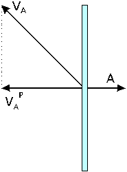
Fig. 12 Projection of the kite velocity vector onto the plane normal vector
The magnitude of the kite velocity vector projection onto the plane normal vector yields (Fig. 12)
(22) 
Since this magnitude can be positive or negative depending on the orientations of kite sail and kite velocities the resulting aerodynamic force can have both orientations too
(23) 
The total force acting on the kite is the sum of all aerodynamic forces and the gravity force
(24)
This force can be transformed into the line-fixed axis system
(25)
where it leads to two angular accelerations of the kite about the pilot
(26) 
(27) 
The empirical damping coefficients take into account the finite thickness of the kite profile. Without these factors the simulated kite would perform undamped (and thus unrealistic) oscillations around its equilibrium. The coefficients have to be chosen from experience in a "visual identification”-manner; a realistic mathematical description based on the actual shape of the profile seems to be pretty difficult.
Differences between the aerodynamic forces of left and right sail lead to a rolling moment of the kite
(28)
The rolling moment about the line results in a corresponding rolling acceleration about the line
(29) 
It has been assumed here that all the kite's mass is concentrated at the two points of action of the aerodynamic forces (see Fig. 11).
Eqs. (26), (27), and (29) can then be integrated twice to come up with the rotational velocities and angles that serve as the six states in this simulation model.
The differential equation system described above has been implemented in a real-time pilot-in-the-loop visual simulation program. RevSim has been programmed in C, uses EGA graphics and should run on every 386 and up. The pilot uses a mouse to emulate both Revolution handles (which is not too easy) and follows the motions of kite, lines, and handles on the screen.
A vertical ("back and forth”) mouse motion causes symmetrical pitch angles of both handles making the kite rise and fall, while a horizontal ("sideways”) mouse input produces asymmetrical handle pitch angles provoking the kite to roll. A handle yaw angle for a slipping motion of the kite can be generated by pressing the left mouse button while doing the horizontal mouse move. The right mouse button in combination with a horizontal mouse movement creates a handle roll angle. The bias (see Eq. (9)) is done by a vertical mouse input with both buttons pressed.
Almost every kite parameter (mass, wingspan, damping, ...) can be changed via a parameter file. "You want to fly a 10 m jumbo revolution with a mass of 10 gram in a 50 m/s hurricane? Give it a try ...”
Real-time is achieved by starting with an arbitrary mean integration rate (of 35/s), by measuring the time for the next 100 integration steps, and by updating the integration time of the Euler-Cauchy-integration routine every 100 steps.
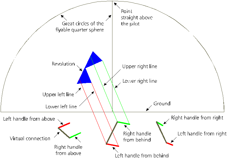
Fig. 13 RevSim screen shot (usually in color)
Fig. 13 gives an impression of the RevSim screen. The flyable quarter sphere is indicated by a fixed half circle and a vertical line. A simple parallel projection has been used to calculate 2D-screen coordinates from the three-dimensional vectors of kite and handles. The kite, the color of which can be chosen arbitrarily, is connected via four visible/invisible lines to a pair of handles seen from behind (the pilot). The view on the handles from above and from the right side are added to create a more realistic imagination of the actual attitude of the handles.
The ground handling of the kite is still very rudimentary. It is a pretty complex task
to model the interaction between kite and ground in a realistic way. If, for example, the
kite "touches” the ground with one wingtip and a horizontal velocity the
immediate reaction of a real-world REVOLUTION® is very dependent on the
friction parameters of the ground (water, sand, grass, ...). RevSim simply prevents the
middle of the leading edge from diving under ground level (). As a
result it is possible to roll the kite around its "center of gravity” on the
ground, which is totally unrealistic on the one hand but a very good exercise for the
inexperienced pilot on the other hand.
Watching experienced REVOLUTION® pilots fly their kites, one can notice
that, whenever they slowly roll their kite around the line (),
they also rotate both hand(le)s around the same axis (
). For
example, if they want to stabilize the kite at a kite roll angle of 90°, meaning that the
left leading edge end points to the sky and the vertical spars point to the left, they
position the left handle above the right handle (
). Being
asked why, they can hardly tell; they just do it, because it works better.
A little experiment might help to better understand the basic principle behind the pilot's behavior.
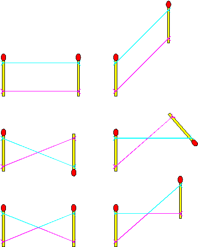
Fig. 14 Stability angles of 180° lead to an aerodynamically unstable system
Connect two matches by two strings (Fig. 14 upper left). The left match could now symbolize one of the handles and the right match could stand for the corresponding vertical spreader spar of the kite. If the kite rises (Fig. 14 upper right) matches and strings still form a parallelogram. The angle of attack is therefore not dependent on the altitude of the kite.
If, as shown in Fig. 14 middle left, the kite has rolled on its back () and the handles did not roll (
), according to
Eq. (12) a stability angle between kite and handles builds up (
).
If now the kite rises (Fig. 14 middle right) the angle of attack is decreased, thus
the lift is increased and therefore the kite rises even more. No stable equilibrium
is possible. The pilot persistently has to actively control the kite to stabilize it at a
certain altitude. This aerodynamical instability is one of the main reasons, why it is
much more difficult to fly a REVOLUTION® on its back than in its normal flying
position.
If the kite has rolled one (or more) full turn(s) (), the
stability angle becomes a multiple of
too (Fig. 14 lower left)
leading to a stable configuration. Even though the lines are crossed the kite rises
parallel to the handles with a constant angle of attack (Fig. 14 lower right). Neglecting
the friction of the lines the handling qualities are identical to the unrolled case.
A simple autopilot has been implemented into RevSim. The stability angle is fed back to the handle roll angle via an integral controller
(30)
in order to keep the stability angle small. As a result the handles try to follow the rolling of the kite if the autopilot is switched on.
RevSim Version 1.2 is available via FTP at
ftp.uni-bremen.de/pub/kites/simulation/revsim/revsim12.zip
and is absolutely free for noncommercial use. As an alternative the author is willing to send anybody a zipped and uuencoded version via email on request.
The four main features to be added in the next RevSim version(s) will be
One of the reasons to develop RevSim was to use it as a testbed for the design of an autopilot for a real-world REVOLUTION®. This will be a hardware-box on the grass controlling all four revolution lines. A video camera with an appropriate pattern recognition algorithm could be used to measure the position and the attitude of the kite, while a model following control system would generate the necessary actuator commands to make the kite perform any figure a human pilot could fly. Could (and should) such a machine win kite championships against human pilots?
| R. Brockhaus | Flugregelung, Springer-Verlag, Berlin, 1994. |
| - | DIN 9300, Normenstelle Luftfahrt im DIN Deutsches Institut für Normung e. V., Beuth Verlag, Berlin, 1990. |
| J. J. Buchholz | Der RevSim, Drachenmagazin, Jahrgang VI, Heft 4/94, Hamburg, 1994. |