
This page was created by Jonas Pfeiffer.
Aerodynamics are a central aspect of most flying vehicles. As such, a deeper understanding may be useful. Therefore I'll now introduce you to some of the most relevant (to aircraft) considerations.
The simplest way to describe the generation of lift in an aircraft is the following: $$L = \frac{\rho}{2} V^2 \cdot S \cdot C_l$$ where $L$ is the lift force, $\rho$ is the air density, $V$ is the velocity, $S$ is the wing area and $C_l$ is the coefficient of lift.
If you want to increase the lift you generate, the best way to do this is to increase speed as the lift generated is proportional to the speed squared. If this is not a possibility for any reason (i.e. you're trying to hit or get off a runway) and we discount all constant influences, the remaining variables are the lift coefficient $C_l$ and the wing Area $S$.
There are two main ways to change your wing area. The first but less used one is to physically
change the entirety or majority of your wing in-flight. One way to achieve this is to use a variable-sweep wing.
In this design, the wing or a part thereof can rotate relative to the fuselage. As the wing area in
the lift equation is measured relative to the airflow, sweeping a wing which is normally swept
backwards forwards effectively increases the area generating lift and therefore the lift
generated.
As the drag generated by a wing is calculated analog to the lift, but with a drag coefficient
Cd instead of the Cl, tilting your wings backwards can reduce drag
(this is not the entire reason for reduced drag - see drag). To make
the most of these two effects, military aircraft like the Grumman F-14 Tomcat (this
picture shows the difference very well), Panavia
Tornado or the MiG-23 feature
such an
installation.
However, as this kind of system is very heavy and is most useful above the speed of sound, it has
not been used on a civilian aircraft (although the Boeing 2707 was at one point intended to
have it)
In the military use case one of the main advantages was the ability to counter the shift in the
center of lift while operating in different Mach regimes. The advancements of computers for
simulation and control purposes has made this obsolete, so that the so far last design that featured
variable-sweep wings is the Tupolev
Tu-160 of 1981.
The second and more common method to increase the wing area of a plane is to use flaps. It is however important to note that not all types of flap increase the area of a wing. Most types generate lift by increasing the camber or improving airflow, which brings us to:
The lift coefficient is a function of
the angle relative to the flow direction (angle of
attack as far as wings are
concerned), the Reynolds number and the
Mach number.
The Reynolds number around airfoils is defined as:
$$Re = \frac {V \cdot c}{\nu}$$
where $Re$ is the Reynolds number, $V$ is the airspeed, $c$ is the chord length and $\nu$ is the
kinematic viscosity.
As before we want to concentrate on a constant-speed scenario, so for our purposes the Reynolds
number is constant for now.
The Mach number is the quotient of local flow velocity (aka airspeed) and the local speed of sound. Again given a constant-speed scenario, the Mach number is constant (discounting changes in speed of sound i.e. from rapid climbs).
What remains then is the angle of attack ($\alpha$).
As you can see in
this
image
,
which is a typical $C_l$ over $\alpha$ graph, the lift coefficient is vaguely proportional to
the angle of attack until it reaches a maximum before then falling off.
This means that you can increase lift by pulling the nose up, but drag also increases (see drag).
While this may be a welcome side effect in a landing scenario, there is
a hard cap to its usefulness, as there is a critical angle of attack.
This angle is the one at which a wing produces its maximum lift coefficient. However if you
increase the angle of attack further, the wing stalls, which means that lift
decreases as the flow separates from the wing. A stall usually occurs at around 15° to 20° $\alpha$.
Stalls are very dangerous, as high angles of attack go hand in
hand with a lot of drag and stall
recovery usually depends on a speed increase. Most often this is done by lowering the nose of the
aircraft to pick up speed and then pulling up again, which causes a further loss in altitude.
As you can surely imagine, a stall close to the ground bears the substantial danger of making ground
contact.
Therefore flying at very high angles of attack is highly unusual, especially in a landing scenario. However there are notable exceptions such as Concorde (whose famous drooping nose is a consequence of this) and most Short Take off and Landing (STOL) planes. Some of these feature slots, a fixed gap behind the leading edge of the wing. This does not contribute to lift at all at zero angle of attack, but with rising $AOA$, the slot allows high pressure air from below the wing to flow above the wing and delay flow separation and thusly the stall. In this fashion, slots can increase the flyable angle of attack by $5$° to $10$° and the maximum lift coefficient by up to $40 \%$. As they increase drag in level flight, their use in commercial applications is limited.
The slat, a close relative of the slot, however is very widely used. The slat is essentially a slot that can be opened as necessary or does so automatically. In this way it allows the use of a lower drag configuration in a cruise situation, while also improving the stall and slow flight characteristics when necessary.
So far I have neglected the two remaining influences slats and flaps can have. Remember the definition of the Reynolds number? It is proportional to the chord length of the wing. The chord line is an imaginary line joining the leading and trailing edges of a wing's profile. By extending the leading and/or trailing edges of a wing, the chord length can be increased. While this alone benefits the generation of lift, the lift coefficient is referenced to the chord length instead of the reference area, when it refers to two-dimensional airfoil sections. Thus the influence of flaps and slats can be twofold, as they increase can increase the wing area as well as its lift coefficient at the same time.
The remaining influence is camber. Camber is the curvature of a wing section and reduces the stalling speed of airfoil sections. Extending leading- and trailing-edge flaps (i.e. Fowler and Krüger flaps as seen on the famous Boeing 747) thus increases the lift coefficient while at the same time decreasing the stalling speed.
For a closer look at what happens when things go wrong (i.e stall, spin etc.) and how you recover from that see dangerous flight situations. For now, a look at drag is in order.
When it comes to airplanes, describing drag mathematically is
fairly simple. Analog to lift, the drag is
$$D = \frac{\rho}{2} V^2 \cdot S \cdot C_d$$
where $D$ is the drag force, $\rho$ is the air density, $V$ the velocity, $S$ is the wing area (you'll also
find this with an $A$ using the frontal area as a reference) and
$C_d$ is the coefficient of drag.
I will mostly concentrate on the drag created by the wings of an airplane in this section. Like the lift coefficient, the drag coefficient is a function of various influences. Unlike the lift coefficient however, the drag coefficient incorporates multiple forms of drag. There are:
Lift-induced drag occurs in all wings. In a
lift generating wing there's a pressure difference between the relatively high pressure air below and
the lower pressure air above the wing. This pressure difference causes a wingtip vortex to form as the air is aiming to
bridge the pressure gap.
This wingtip vortex changes the effective airflow direction, thusly effectively decreasing the angle of
attack. The angular difference between free stream airflow and effective airflow is called induced downwash
angle (as seen here).
The local lift vector is therefore tilted slightly backwards, meaning on one hand, that the necessary angle
of attack to achieve a certain lift is increased (by a small amount) and on the other hand, that a drag
force component is produced.
Mathematically, the induced drag is
$$D_i = \frac {L^2}{\frac{\rho_0}{2}\cdot V_E^2 \cdot \pi \cdot b^2}$$
with $L$ as the lift force, $\rho$ as air density, $V_E$ the equivalent airspeed and $b$ as wingspan
(planar wing with elliptical lift distribution).
As you can see, the induced drag is proportional to the lift squared. This is because the induced drag is
the product of the lift and the angle of deflection of the lift force, which is in itself a function of the
lift.
To compare the induced drag with other sources of drag, a drag coefficient can be calculated as follows
$$ C_d,i = \frac{C_l^2}{\pi \cdot AR}$$
$AR$ is the aspect ratio of a wing. It
is defined as the wingspan squared divided by the projected wing area.
This means, that a long thin wing reduces the induced drag. The pressure difference is lower this way as the
lift distribution is stretched more. The fact that induced drag decreases with speed (lower $C_l$
needed to maintain lift) and this
is why gliders usually have very sleek wings. However, this is mostly limited to slow and very high flying
planes, as parasitic drag is also increased, meaning it is only advisable if
you need to generate a maximum amount of lift from your wings and you can't significantly increase your
speed.
Other means of trying to reduce induced drag are winglets and other wingtip devices aimed at
reducing the wingtip vortex.
Parasitic drag is considered as such as it is not
a consequence of the generation of lift, but rather created by an object moving through a fluid.
It occurs in three forms, form drag, skin friction drag and profile drag.
Form drag is directly dependent on the geometric shape of an object. Thin and sleek ("streamlined") bodies
have lower drag than short and voluminous geometries. Also steps and other discontinuous forms should be
avoided as these allow boundary layer separation
and the formation of vortices.
Skin friction drag stems from the fact that the air molecules in the boundary layer moving around an object will
stick to said object. This in turn causes molecules in the next layer to be decelerated and so on. At some
point along an airplane the boundary layer, which is usually laminar and thin, detaches and the boundary
layer
becomes turbulent, increasing drag.
There are two main possibilities to decrease skin friction drag: ensuring laminar flow wherever possible and
lengthening the body while reducing the frontal area.
Wave drag as the name implies is caused by shockwaves.
These shockwaves typically start to form in the transonic speed regime (beginning at Mach $0.8$),
however it can present
itself at lower speeds (over the critical Mach
number).
Their occurrence is caused by some of the airflow along an airplane being supersonic. This can occur even in
aircraft well below the speed of sound as the air accelerates along the body (i.e. following curves). Upon
an aircraft exceeding its critical Mach number, drag increases suddenly.
This effect, sometimes also known as compressibility, led to
speculation
about a so called sound barrier, as it was impossible to (the vast majority of) World War II era planes to
even come close to the speed of sound. The first time an airplane officially surpassed the speed of sound
was on October 14, 1947, as Chuck Yeager at the
controls of the (deliberately) bullet-shaped Bell X-1
broke the sound barrier
(watch this and read that) .
The reduction of wave drag requires some thought when designing a plane. One of the most popular solutions
is to sweep the wings (backwards most of the time).
In essence, this makes the wing longer and thinner in relation to the airflow, lessening the speed
increase. It also allows the use of a wing profile suited to use at lower operating speeds where camber and
thickness are important.
An additional advantage especially compared to our next solution, the very thin wing, is the possibility to
still use the wings for storage (i.e. fuel, landing gear, weapons). Very thin wings also accelerate the air
much less, so that wave drag occurs more evenly and predictably across the whole airframe.
Our third solution to the wave drag problem is the application of the so called area rule. The essence of the area rule is that the cross sectional area (including fuselage and wings) of a plane must be distributed in such a fashion that there are no discontinuities, making smooth transitions necessary. This is especially of importance at the wing/fuselage joint and one popular solution is thinning the fuselage of your airplane in a coke bottle shape (looking at you XF-92). Sometimes anti-shock bodies were used instead (i.e. Convair 990 Coronado), but they are rare in modern aircraft.
Overall after covering the three kinds of drag, we have established, that induced drag dominates at low
airspeeds, while getting weaker at higher speeds at which parasitic drag dominates. Wave drag then causes a
sudden increase in drag.
A typical resulting drag over airspeed graph can be seen here
(omitting wave drag). The minimum of the total drag curve is the airplane specific most efficient flight
speed.
This
image shows the influence of wave drag in the transonic
region (Mach $0.8$ to $1.2$).
In the quest of designing a good airplane it is therefore of paramount importance to match plane and wing
design to speed, altitude and flight profiles.
Besides the wings and the fuselage, there are other influences on drag in an airplane.
Some things like flaps are used only in certain flight conditions (take off and landing in this case) or are
necessary for other reasons (i.e. maneuvering on the ground).
One of the most obvious things is the landing gear
of an aircraft. Most modern airplanes have retractable tricycle landing gear to reduce drag in
cruise. Fixed
landing gear increases the frontal area and worse still creates vortices, which dramatically increase drag.
Related accessories such as landing gear doors may also negatively impact aerodynamic performance.
Other variables are flaps and slats, but air
brakes, spoilers, flaperons, spoilerons and all other control surfaces create drag
as well.
In case of three of them (air brakes, spoilers and spoilerons), increasing drag is actually a feature, as
they are used to slow the aircraft down. Air brakes simply increase drag (i.e. by increasing the frontal
area) and come in various forms (i.e. the split
rudder of the Space Shuttle, the split
tail-cone of the BAe 146 or the dorsal
air brake of the McDonnell
Douglas F-15 Eagle).
Spoilers create drag and decrease lift and are a feature helping virtually every commercial airliner in
existence (i.e. the spoilers
of an Airbus A321) to land.
Spoilerons combine the function of an aileron and a spoiler. Often the spoilers used to spoil the wing after
landing are used as spoilerons in the air. These can augment or substitute for ailerons. At high speeds and
in thin wings, ailerons induce a big twisting moment, which could cause roll reversal. Spoilerons work by
asymmetrically reducing the lift and thusly inducing a rolling moment. This also creates a yawing moment.
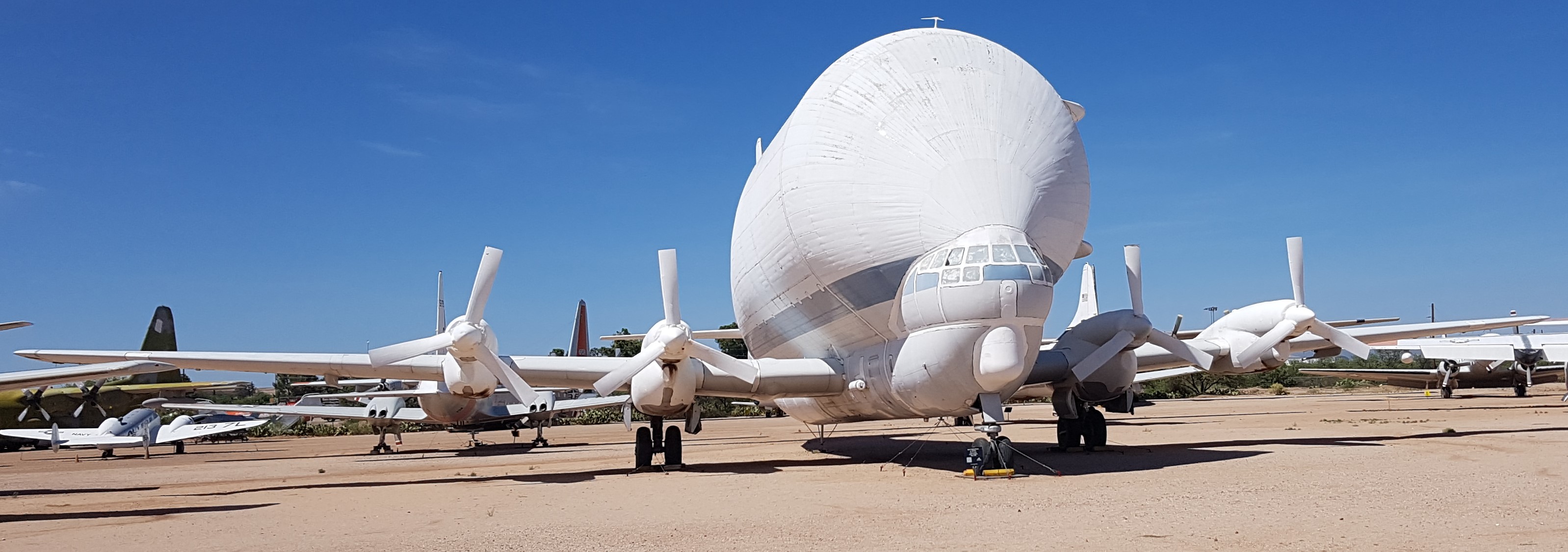
The featured image depicts the very aerodynamic Aero Spacelines Super Guppy which
was first used by NASA to transport rocket parts.
This picture was taken at Pima Air & Space Museum in Tucson, AZ in 2018.
Pima is one of the biggest air and space museums in the world and features favorable storing conditions and
a lot of space.
It is also located close to the
biggest aircraft boneyard in the world.
#/media/File:Drag_curves_for_aircraft_in_flight.svg)
#/media/File:Qualitive_variation_of_cd_with_mach_number.png)
#/media/File:STS-116_landing_port_behind.jpg)
#/media/File:Eurowings_bae146-300_d-aewb_arp.jpg)
#/media/File:F-15_Eagle_landing_with_the_speed_brake_up.jpg)
#/media/File:Air_Jamaica_A321_landing_spoilers_opened.jpg)